
Each DSCT32 current input transmitter provides a single channel of analog input which is filtered, isolated, amplified, and converted to a process current output. Signal filtering is accomplished with a five-pole filter, which provides 80dB per decade of normal-mode rejection above 100Hz. An anti-aliasing pole is located on the field side of the isolation barrier, and the other four are on the process loop side. After the initial field-side filtering, the input signal is chopped by a proprietary chopper circuit. Isolation is provided by transformer coupling, again using a proprietary technique to suppress transmission of common mode spikes or surges.
Special input and output circuits on the DSCT32 transmitters provide protection against accidental connection of power-line voltages up to 240VAC and against transient events as defined by ANSI/IEEE C37.90.1. Signal and loop power lines are secured to the module using screw terminals, which are in pluggable terminal blocks for ease of system assembly and reconfiguration.
The modules have excellent stability over time and do not require recalibration, however, zero and span settings are adjustable up to ±10% to accommodate situations where fine-tuning is desired. The adjustments are made using potentiometers located under the front panel label and are non-interactive for ease of use.
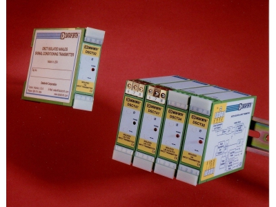
DSCT32
Analog Current Input Transmitters
Dataforth
- Accepts Milliamp Level Signals
- Process Current Output
- 1500Vrms Transformer Isolation
- ANSI/IEEE C37.90.1 Transient Protection
- Input and Output Protected to 240VAC Continuous
- Up to 60V Loop Voltage
- 160dB CMR
Details
Specifications
Input Type
0 - 20 mA
4 - 20 mA
4 - 20 mA
# of Inputs
1
Output Type
4 - 20 mA
Max Bandwidth
100 Hz
Isolation
Yes
Supply Power
12 - 60 V DC
Models
DSCT32-01
Input Range: 4 to 20 mA
DSCT32-02
Input Range: 0 to 20 mA
Downloads
DSCT32 Analog Current Transmitter V2
DSCT32
DSCT Diagram
DSCT Intro
AN101 RMS_Voltage_Current
AN105 Resistance Temperature Detector V2
AN121 RiseTime vs BW
AN126 Tuning_Surge_Tank_Level_Control_Loops
AN127 OP-Amp Errors, another View
AN128 RMS Revisited
AN129 Harmonics and utility costs
Hysteresis Specifications
Data Acquisition Systems Accessories
Faraday's Law of Induction
Signal Conditioner Surge Withstand Capability
Sample Test Report
Signal-to-Noise Ratio, SNR
Signal Conditioning Measured vs Combinational Error
When Good Grounds Go Bad
Why Should Sensors Be Isolated